
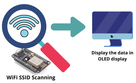
NodeMCU based WiFi Network Scanner with OLED Display
In this tutorial, we are going to learn about building a WiFi scanner. This will be a NodeMCU based WiFi Network Scanner with OLED Display. It will scan and display the existing WiFi networks with the help of ESP8266 nodemcu module. It will show the SSID’s on the Arduino Serial monitor. The values will also be displayed on the OLED display.
Components Required
- SSD1306 OLED 0.96inch Display x 1 [BEST BUY]
- ESP8266 NodeMCU x 1 [Best Buy]
- Jumper cables [Best Buy]
ESP8266 based NodeMCU board
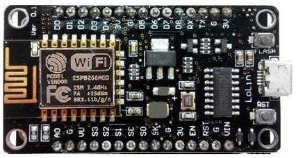
ESP8266 chips are popular in the field of IoT, which have better quality and lower price than other models. The core of this module is ESP8266 EX, which is actually located under this metal shield. Metal is placed in this module to reduce noise as well as protect sensitive SMD components. These modules are produced in different series, including esp01 and esp12. In fact, the difference between the models is the number of GPIOs as well as their memory. although usually the differences in appearance are usually recognizable. These modules support the internal WIFI network. The ESP8266 has 13 GPIOs with an analog input (A0).
SSID Concept
SSID stands for Service Set IDentifier and its the name of your network. If you open the list of Wi-Fi networks on your laptop or phone, you will see a list of SSIDs. Wireless routers broadcast SSID access points so that surrounding devices can find and display them. SSIDs can be up to 32 characters long, but there is no minimum size limit. Depending on your router brand manufacturers create default SSIDs which is a combination of company name with random numbers or letters.
OLED SSD1306 Display
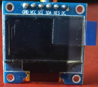
OLED displays are commonly used in IoT and other embedded projects to display text and different values. These modules come in a variety of sizes depending on the size of the driver, one of the most popular being the SSD1306. There are different types of OLEd’s available in the market, mostly 0.96 and 1.3 inch sizes are widely used in projects. Also, these OLED use SPI/I2C as a communication protocol. In this tutorial we are using a SSD1306 OLED display. Its a 0.96-inch monochrome display with 128 x 64 pixels. The OLED display does not require backlighting, which results in a very good contrast in dark environments. Also, its pixels consume energy only when turned on, so the OLED screen consumes less power than other displays.
Working
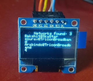
In this project, we will print the existing SSID values in OLED display. After programming the board, all available channels will be scanned every few seconds and the values will be printed on the screen. Due to the size of OLED display only three of the SSIDs that have the highest signal strength are displayed with the total number of networks shows at the top of the page.
Required Libraries
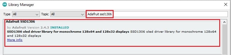
The code needs 2 libraries to compile and run. Locate Sketch -> Include Library -> Manage Libraries
You can download Arduino IDE from Here.
Search for “Adafruit SSD1306” and click on Install
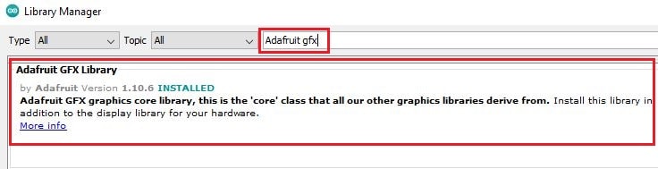
Then search for the word “Adafruit GFX ” and install it as well.
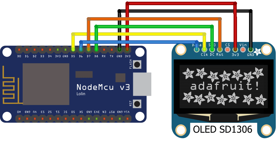
Connection
Below table shows connectivity between OLED display and NodeMCU using SPI protocol.
NodeMCU | OLED Display |
D5 | SCL |
D6 | SDA |
D7 | RES |
D8 | DC |
+5V | VCC |
GND | GND |
Code Analysis
In this section, we will review the important parts of this code. In the first few lines, we introduce the required libraries.
#include <SPI.h>
#include "ESP8266WiFi.h"
#include <Adafruit_GFX.h>
#include <Adafruit_SSD1306.h>
Below line of code is used to specify the dimensions of the display.
#define SCREEN_WIDTH 128
#define SCREEN_HEIGHT 64
In this line, we have set the ESP radio mode to STATION MODE for scanning.
WiFi.mode(WIFI_STA);
In this section, we display the SSID and RSSI values in the monitor serial. RSSI is actually the signal strength of the network.
Serial.print(i + 1);
Serial.print(": ");
Serial.print(WiFi.SSID(i));
Serial.print(" (");
Serial.print(WiFi.RSSI(i));
Serial.print(")");
Serial.println((WiFi.encryptionType(i) == ENC_TYPE_NONE) ? " " : "*");
In this section, we will print the total number of available WIFI networks at the top of the screen on the OLED display.
display.setTextColor(SSD1306_WHITE);
display.setCursor(25,0);
display.print("Networks: ");
display.print(n);
Finally, we print the SSID values in each row.
display.setTextColor(SSD1306_WHITE);
display.setCursor(0,8);
display.println(WiFi.SSID(0));
display.println(WiFi.SSID(1));
display.println(WiFi.SSID(2));
display.println(WiFi.SSID(3));
display.println(WiFi.SSID(4));
display.setCursor(0,0);
display.display();
display.clearDisplay();
Complete Code
You can download the code from below link. Open the code using Arduino IDE and upload the code in NodeMCU. If you are not sure how to upload the code, then check out the article below.
Easy NodeMCU Programming with Simple Steps

Suggested Projects:
- DHT11 Sensor with ESP-NOW and ESP32
- Smart Switch using Blynk | IoT Based WiFi Switch
- PIR based Motion Switch | PIR Sensor Light
- Touch Based Switch board using TTP223
- DHT11 based Temperature Humidity Monitoring IoT Project
- IoT based Door Security Alarm Project with Blynk
- Telegram NodeMCU based Home Automation
- NodeMCU Blynk Feedback Switch with Physical Switch Status
- NodeMCU ESP8266 IoT based LPG Gas Leakage Alarm
- Smart Doorbell using ESP32 Camera
- DS18B20 with NodeMCU Local WebServer
- How to read DHT11 sensor data using Blynk
- ESP32 based Switch Notification Project using Blynk
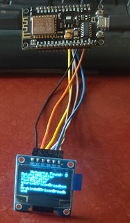
Building & Testing
Once you power the NodeMCU the Wi-Fi network scanner will start working as a station mode and scan for all available networks. Then it will show the data in the OLED display. We are using SPI protocol, so that the SCL and SDA pins will be connected to pins D5 and D6.
Conclusion
In this project, we managed to scan and display the surrounding Wi-Fi networks, and display these values in the OLED display. In this project, the ESP8266 board and the SSD1306 display module were used. If you are a beginner do try this and provide your feedback. Don’t forget to share this tutorial.