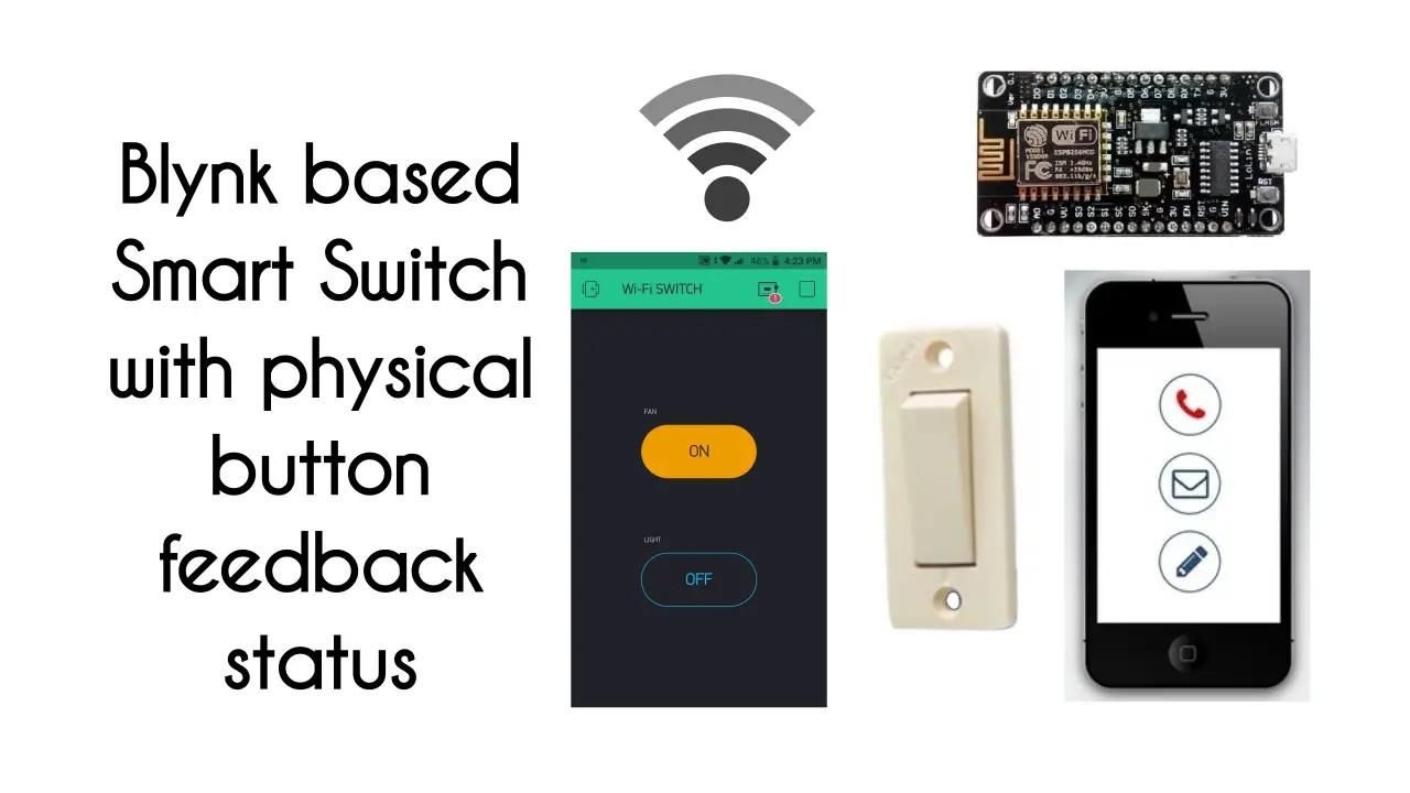
Introduction
These days there are different types of switches available in the market. Some switches can be accessed by smartphones using certain apps. In this article we will see how to build a NodeMCU Blynk Feedback Switch with physical button feedback status.
This is simple and easy to build. It can be used at home in real time and can be useful for disabled and older people. Any beginner who has a knowledge of Arduino code and wifi modules can build this projects easily.
Materials Needed
For building this project, below components are needed. These are easily available in the market.
- ESP8266 NodeMCU x 1
- 2 Channel Relay Module x 1
- Push button switches x 1
- Led’s (Red & Green) x 2
- Resistor 330Ω (1/4w) x 2
- Resistor 10KΩ (1/4w) x 2
- Mobile Charger (5v/1A) as power supply
- Jumper Wires
- Breadboard
How it Works?
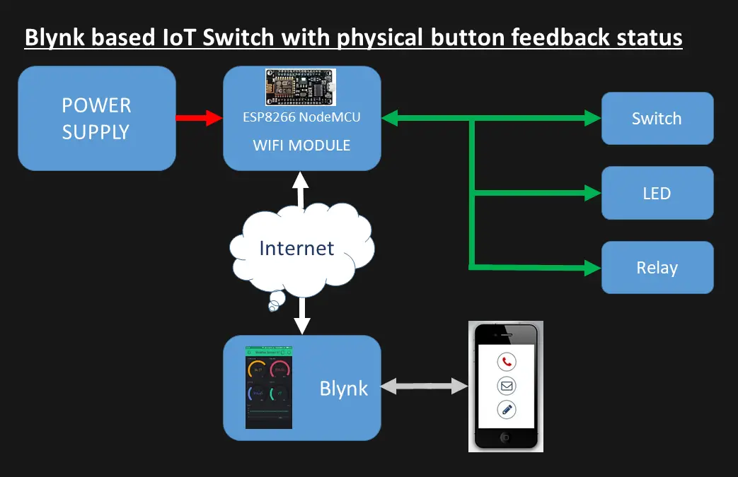
The working of this project is simple. Here NodeMCU is the brain of this project which takes action as per the code. This wifi module gets connected with internet and sends/receive data from blynk app.
Once the project is powered up you the code will check if internet is available. If internet is available and the connection is established then Green led will glow. In case internet is not available Red light will glow. Relays will control the AC appliances and switches can also be used to turn on/off the devices.
The state change in switches will be reflected in blynk app. Alternatively you can control the devices using blynk as well. In case of power failure or reset the device will get reconnected as sync the state from blynk.
Module Functions
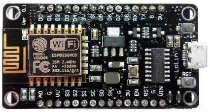
NodeMCU:
This the used for controlling the appliances and other components connected. This module helps in connecting with internet and sending / receiving data form blynk app.
Relay Module:
In this project we are using 2 channel relay module. You can also use 4 channel if you wish to control 4 devices. This is used for switching AC devices as per the signal from NodeMCU.
Led’s are used for visual indications. Resistors are used as current limiting and switches are used for switching devices.
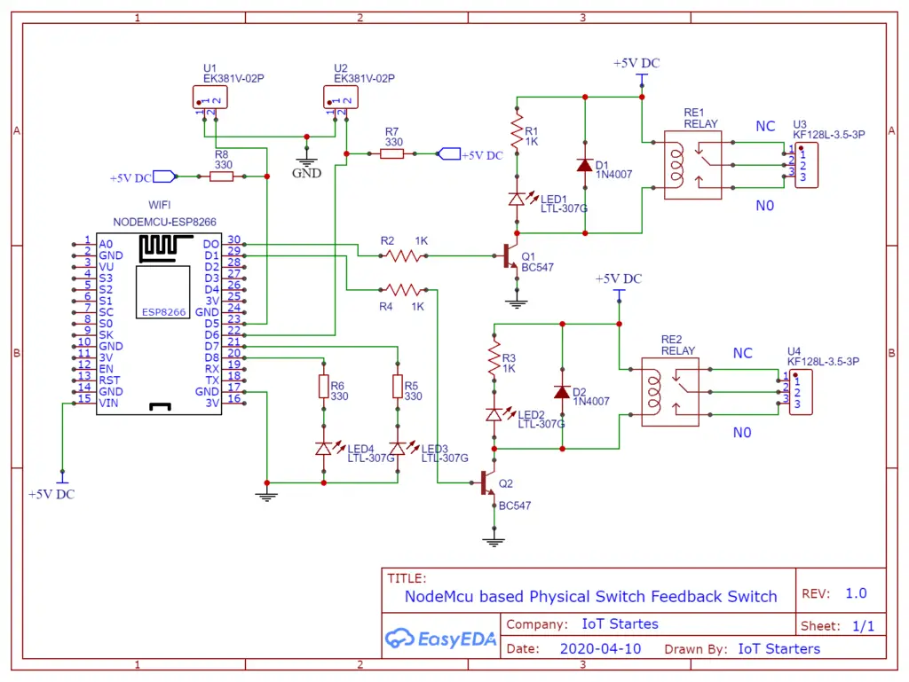
Circuit Diagram
Below circuit diagram can be built on a PCB. It is easy to build a relay module.
Must Read:
Blynk Setup
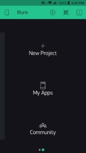
Open Blynk app and tap on New Project
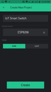
Give a project name and Select the Device Type
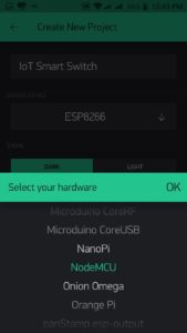
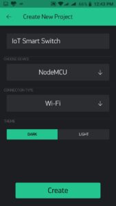
Select your hardware as NodeMCU
After filling up all the details just tap on Create
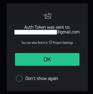
Auth Token will be sent to registered email address
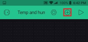
Tap on the button below to add widgets
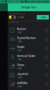
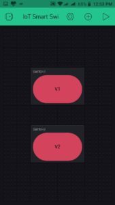
Select Button or Styled Button. Since we will be configuring two switches hence we will select in two numbers.
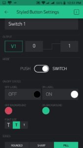
Once you select switches, provide the name for that switch and configure the remaining a shown for both the switches.
After configuration you can press the triangular button to connect your blynk project with your hardware.
Code
The code is available for download here. Just update SSID, Password and Auth Token and upload the code in NodeMCU. You will receive an email from blynk regarding auth tiken while setting up the project in Blynk app.
// Your WiFi credentials.
// Set password to "" for open networks.
char ssid[] = "Your Network SSID" ; // update SSID
char pass[] = "Network Password" ; // update password

// You should get Auth Token in the Blynk App.
// Go to the Project Settings (nut icon).
char auth[] = "Auth Token" ; // Update Auth Token
Complete Code
/***************************************************************
This project is based on NodeMcu ESP8266
This works with Internet or without Internet with physical switch status Feedback
Automatic and Manual switching Home Automation project using Blynk IoT Platform
***************************************************************/

#include <ESP8266WiFi.h>
#include <BlynkSimpleEsp8266.h>
BlynkTimer timer;

//Pin assignments
#define switch_1 14 // D5 Pin of NodeMcu
#define switch_2 12 // D6 Pin of NodeMcu

#define relay_1 16 //D0 Pin of NodeMcu
#define relay_2 5 //D1 Pin of NodeMcu

#define LED1 13 //D7 Pin of NodeMcu
#define LED2 15 //D8 Pin of NodeMcu

int MODE = 0;

// Your WiFi credentials.
// Set password to "" for open networks.
char ssid[] = "NEtwork SSID";
char pass[] = "Network Password";

// You should get Auth Token in the Blynk App.
// Go to the Project Settings (nut icon).
char auth[] = "Auth Token";

int switch_1_ON = 0;
int switch_2_ON = 0;

BLYNK_WRITE(V1)
{
int pinValue = param.asInt(); // assigning incoming value from pin V1 to a variable
digitalWrite(relay_1, pinValue); // process received value
}

BLYNK_WRITE(V2)
{
int pinValue = param.asInt(); // assigning incoming value from pin V2 to a variable
digitalWrite(relay_2, pinValue); // process received value
}

void internet() //When this device connects with internet
{
//**************************************
//Switch 1 configuration
//**************************************
if (digitalRead(switch_1) == LOW)
{
if (switch_1_ON == 0 )
{
digitalWrite(relay_1, LOW);
Blynk.virtualWrite(V1, 0);
switch_1_ON = 1;
}
}

if (digitalRead(switch_1) == HIGH )
{
if (switch_1_ON == 1)
{
digitalWrite(relay_1, HIGH);
Blynk.virtualWrite(V1, 1);
switch_1_ON = 0;
}
}
//**************************************
//Switch 2 configuration
//**************************************
if (digitalRead(switch_2) == LOW)
{
if (switch_2_ON == 0 )
{
digitalWrite(relay_2, LOW);
Blynk.virtualWrite(V2, 0);
switch_2_ON = 1;
}
}

if (digitalRead(switch_2) == HIGH )
{
if (switch_2_ON == 1)
{
digitalWrite(relay_2, HIGH);
Blynk.virtualWrite(V2, 1);
switch_2_ON = 0;
}
}
}
//********************************************

void no_internet() //When this device doesn't gets internet
{
digitalWrite(relay_1, digitalRead(switch_1));
digitalWrite(relay_2, digitalRead(switch_2));
}

void Blynk_status() // called every 3 seconds by SimpleTimer
{
bool isconnected = Blynk.connected();
if (isconnected == false)
{
MODE = 1;
digitalWrite(LED1, HIGH);
digitalWrite(LED2, LOW);
}
if (isconnected == true)
{
MODE = 0;
digitalWrite(LED1, LOW);
digitalWrite(LED2, HIGH);
Blynk.syncAll();
}
}

void setup()
{
Serial.begin(9600);
pinMode(switch_1, INPUT);
pinMode(relay_1, OUTPUT);

pinMode(switch_2, INPUT);
pinMode(relay_2, OUTPUT);

pinMode(LED1, OUTPUT);
pinMode(LED2, OUTPUT);

//*****************************************

digitalWrite(LED1, HIGH);
delay(200);
digitalWrite(LED1, LOW);
delay(200);
digitalWrite(LED2, HIGH);
delay(200);
digitalWrite(LED2, LOW);
delay(200);
digitalWrite(LED1, HIGH);
delay(200);
digitalWrite(LED1, LOW);
delay(200);
digitalWrite(LED2, HIGH);
delay(200);
digitalWrite(LED2, LOW);
delay(200);
digitalWrite(LED1, HIGH);
delay(200);
digitalWrite(LED1, LOW);
delay(200);
digitalWrite(LED2, HIGH);
delay(200);
digitalWrite(LED2, LOW);
delay(200);
digitalWrite(LED1, HIGH);
delay(200);
digitalWrite(LED2, LOW);
delay(200);
digitalWrite(LED2, HIGH);
delay(200);
digitalWrite(LED1, LOW);
delay(200);

WiFi.begin(ssid, pass);
timer.setInterval(3000L, Blynk_status); // check if connected to Blynk server every 3 seconds
Blynk.config(auth);
}

void loop()
{
if (WiFi.status() == WL_CONNECTED)
{
Blynk.run();
}

timer.run(); // Initiates SimpleTimer
if (MODE == 0)
internet();
else
no_internet();
}
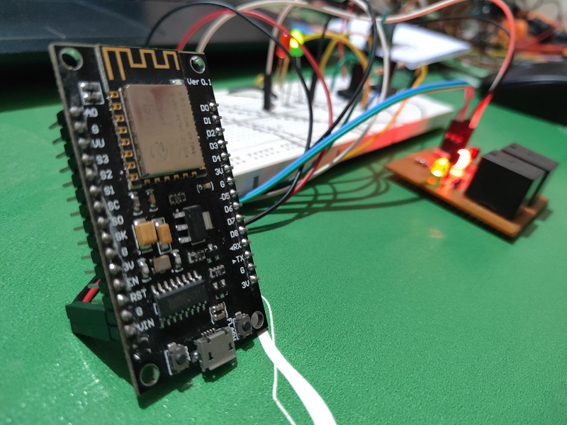
Construction
Building this project is simple and easy. Get all the required materials and connect it as per the circuit diagram.
Testing
When the project is powered on, first it will check for internet connectivity and tell you the status accordingly. You can refer the video below for complete project.
Conclusion
This project NodeMCU blynk feedback switch can be used at home and will be very effective. The major advantage of this project is getting a feedback status of the physical switch. This can be controlled via blynk app from your mobile. In case of power cuts it will restore the blynk switch state as well. The components used for building this project is easily available in stores. It’s really a fun making this project.
How can I use actual switch instead of a push button, would you provide some information on that.
Hi,
Yes you can use normal ac switches. Just connect the 2 wires as same as connected with pushbutton switch.
Sir remote ke switch Ki Tarah kam Karen Aisa switch banaa kar boliye na
Thank you sir I will try today