
PIR based motion switch under ₹160 ($2.5)
Introduction
Today the world is moving toward contact less devices. These devices make life easier and also help us to save resources, energy. We are going to discuss a simple project which will help you to save money and resources. PIR based motion switch is one of the simple and effective project.
PIR based motion switch is used to trigger light or any other device when a human comes in motion across the range of PIR sensor. This is a basic circuit with some basic components.
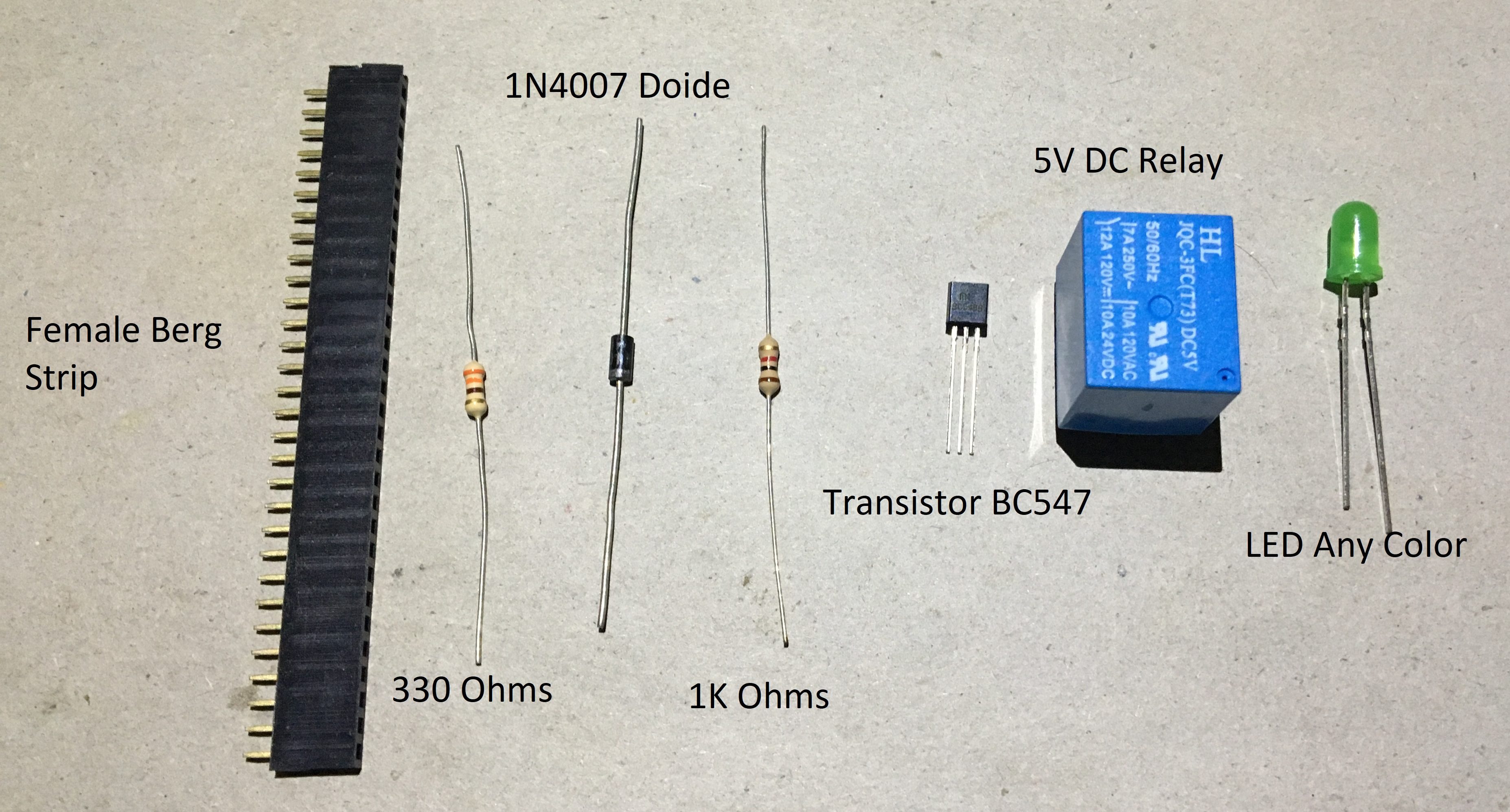
Components Required in PIR based motion switch
- PIR Sensor x 1
- Relay 5V DC x 1
- Diode 1N4007 x 1
- Transistor BC547 x 1
- Led (Any color) x 1
- Resistor 330Ω x 1
- 5V DC power supply (You can use a mobile charger upto 1A)
- Small Copper board x 1
You can buy the above components from any electronic store like Aliexpress or from any local store.
Schematics
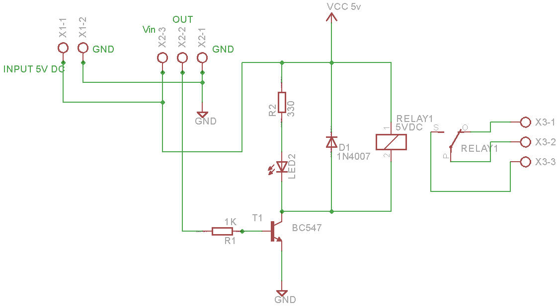
Circuit Diagram
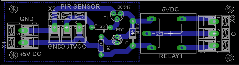
PCB View
Setting it up
This project doesn’t need any programming. It is easy to connect and set up. the entire project can be easily assembled on copper PCB. If you are just trying to understand the concepts then you can use bread board to align the components as per the circuit diagram.
In PIR modules we see can see two small potentiometers. One for changing sensitivity and the other one is for changing the delay time.
The two pots are marked as Sx and Tx. Where Sx is meant for adjusting sensitivity and Tx is for changing time delay.
In PIR module you can also see jumpers (in some modules they might not be available). There are two types of jumper settings available.
Repeatable: Once the sensor gets triggered, if the sensor find a continuous motion in its rage then it will send High signal. Which means the device will be kept on till it finds the motion
Single: Here the device will be turned off after a certain delay which is set. It will be irrespective of any continuous movement within the range of sensor.
Uses of components:
PIR sensor is used to sense motion and sends a signal to relay for switching.
We have used two resistors 330 ohms which acts as a current limiting resistor for LED. The other resistor of 1K ohms is connected to transistor for the same.
A transistor BC547 is used to trigger the relay. The transistor is used as a switch for the relay.
A diode of 1N4007 is being used to avoid reverse flow of current across the relay. This is also known as free wheel diode.
We are using a 5V DC relay for switching on/off heavy electrical appliances. We have also used a LED parallel to relay ti check the switching state. The entire project uses few components.
You can use a 5V DC mobile charger for power supply. It is economical and robust.
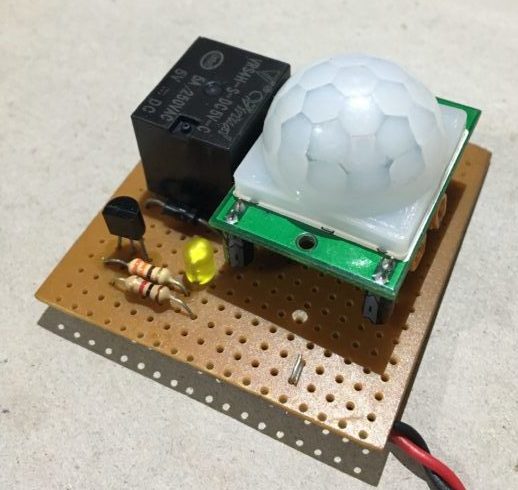
Testing
Below is a prototype which is built. You can use any circuit design tool and get custom PCB’s. For testing connect the circuit with 5V power supply. Once the circuit is powered up it will stabilize within 30-60 sec. Then if you wave the hand in front of sensor the led will be powered on. It will also power off after delay time. By default the sensor is in repeatable mode.
Conclusion
This project can be good for beginners. This will give a good idea about PIR sensor and its concept of working. Uses few components which is very economical. This can save manual effort for switching lights and save electricity.
We hope you enjoy building this project and comment below that where you have used this project.

