
Controlling a servo motor using Raspberry Pi Pico
Controlling a servo motor using Raspberry Pi Pico depends on learning electronic concepts, i.e. PWM bandwidth modulation. The servo motor is provides angular movement and can be controlled using coding. You can also adjust the desired angle using the code very precisely.
Materials Required
- Raspberry Pi Pico x 1
- Servo Motor SG90 x 1
- Jumper Cables x 1
Raspberry Pi Pico
Raspberry Pi Pico board uses widely used communication protocols to communicate with other hardware.
- It has two UART
- It has two I2C
- It has two SPI
- Has a PWM channel
- A timer with four alarms
- Has a real time counter
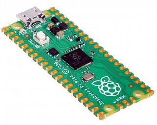
The Pico Raspberry Pi board uses the smallest components to support the RP2040 chip, from the crystal to the power supply. Most RP2040 microcontroller pins are on left and right side on the board along with IO pins. The four IO pins of the RP2040 are used for internal operations. Due to the placement of Raspberry Pi board and GPIO bases, it can be installed on other places to execute and build projects. To do this, 40 rows of standard header pins are spaced 0.1 apart from each other and even fit all standard board.
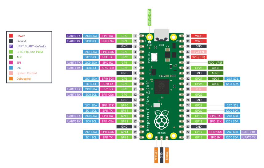
Pico uses a BUCK-BOOST SMPS to supply 3.3 volts to power the RP2040 and the internal circuit. For this reason, there is considerable flexibility to apply voltage. You can easily use a single-cell lithium battery or a AA 3-cell battery to power it up. Raspberry Pi Pico board is made of 40 rows of pin headers with 21X51 style with a thickness of 1 mm. Among these 40 pins, 26 pins are exclusively with a voltage of 3.3 volts for GPIO, i.e. input and output pins. Out of these 26 pins, 23 are digital pins and 3 pins support ADC. Digital pins are used to connect sensors and modules to digital inputs and outputs. Analog pins with ADC interface are used for analog sensors. The most important point is, all pins have a fixed voltage of 3.3 volts.
Raspberry Pi Pico PWM
Raspberry Pi Pico has PWM capability on all GPIO pins. When a GPIO pin is set to PWM mode, the output of each pin varies with frequency cycle. The lowest PWM frequency output is 10Hz. If the slow cycle is always 1, it means that the frequency wave is always HIGH. PWM output frequency is equal to 1 / PERIOD.
Servo motor
Servo motor is a small and lightweight gear module with high output power. The output shaft of the Servo motor SG90 has the ability to rotate at an angle of 180 degrees in each direction by 90 degrees. With a pulse of 2 milliseconds only in the right direction, in “90-” with a pulse of 1 millisecond it will rotate only in the left position.
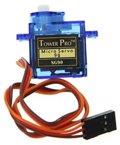
The operating voltage of Servo motor SG90 4. 8v to 5 volts DC. Servo motor has 3 pins GND, VCC and Signal, respectively. The brown wire is GND, the red wire is based on VCC and the orange wire is based on signal (S). Note that if you intend to start more than one servo motor, do not use the Arduino power supply at all and use an external power supply.
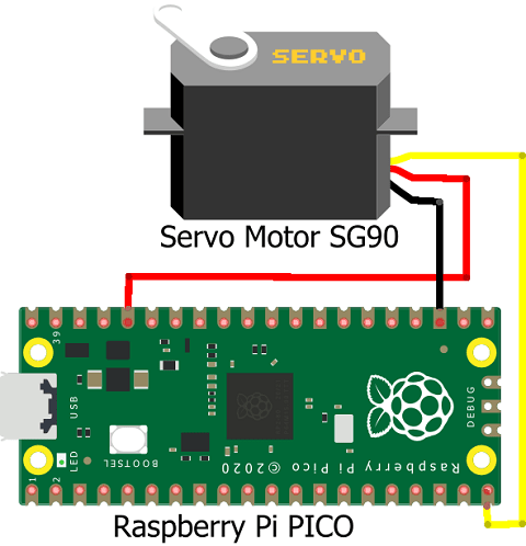
Connection
We can use all GPIO pins to connect with the servo motor to Raspberry Pi Pico.
- The brown wire, which is the same as the GND, is connected to the GND base of the Raspberry Pi Pico.
- Red wire of servo will be connected to pin 36 of Raspberry Pi PICO as VCC
- Connect the orange wire to pin 20 (GP15) of Raspberry Pi PICO
Coding Raspberry Pi Pico with micro python
Before doing anything, we must install Thonny micro python is your computer. Then hold the BOOTSEL switch before connecting the Raspberry Pi to your computer.
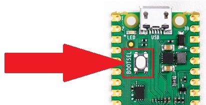
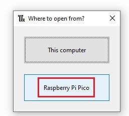
After connecting the MICRO USB cable with your computer release your hand from the BOOTSEL switch . This will detect the Raspberry Pi Pico and its window will open.
We have created a nice tutorial and you can get step by step details there.
Configuring Raspberry Pi PICO with Thonny IDE
Python coding for servo motor
The first step in Python is to call the required parameters from the machine library.
from machine import Pin, PWM
import utime
MID = 1500000
MIN = 1000000
MAX = 2000000
In the next step, we define the PWM pins and an LED in the output.
led = Pin(25,Pin.OUT)
pwm = PWM(Pin(15))
Now we specify the PWM frequency.
pwm.freq(50)
Define the slow cycle on the MID mode, i.e. the lowest mode.
pwm.duty_ns(MID)
Inside the while true loop, we specify the slow cycle at the lowest possible state. Then wait a second. Then define the midpoint on the MID and wait a second. In the next mode, we set it to the maximum possible mode.
pwm.duty_ns(MIN)
utime.sleep(1)
pwm.duty_ns(MID)
utime.sleep(1)
pwm.duty_ns(MAX)
utime.sleep(1)

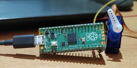
Building and Testing
Some more interesting Projects:
- Configuring BMP280 Sensor with Raspberry Pi
- IoT Pulse Oximeter Using NodeMCU MAX30100 & Blynk
- Configuring Motion Sensor with Raspberry Pi Pico
- Weather Station with BMP280 Sensor and Raspberry Pi Pico
- DIY Digital clock with RTC DS1307 and Raspberry Pi PICO
- IoT Security Camera using ESP32-Cam Blynk and PIR Sensor
- Reading built in Temperature sensor values of Raspberry Pi PICO
- ESP8266 based IoT Panic Alarm for Old Age People using Blynk
- How to send sensor data to Thingspeak using Raspberry Pi
- ESP32-CAM based Email Notification System
- ESP32 based Gas Leakage Detection using Email Notification
- IoT based Motion Detection Alarm using ESP8266 and Blynk
- Smart Switch using Blynk | IoT Based WiFi Switch
- Controlling ESP32 via Bluetooth using Blynk
- IoT Heart Rate Monitoring with ThingSpeak Platform
- IoT based Fire Security Alarm System using NodeMCU
Summary
This is a simple tutorial where we have connected a servo motor with Raspberry Pi Pico. We are using micro python to control the movement of server motor using PWM (Pulse Width Modulation) technique. This is very useful for beginners to understand the concept of PWM using micro python.