Smart Switch using Blynk
Introduction
This is an era of smart devices like smart phone, smart home appliances and other smart devices. To control these devices we have developed many smart switches which works with smartphones. Today we are going to discuss about building one of the WiFi Switch which will be very cost effective and can be used on real time. This is a smart switch using blynk.
This switch is build using ESP8266-01 module. This is a cheapest wifi module available on the market today. There are many variants available. In this project we will be using the basic variant.
We will use Blynk app to monitor and access the hardware. To connect with internet we will use wifi module. Will code using arduino IDE. If you are new to blynk then you can check the article below to know what is blynk and how to configure it.
Must Read: What is Blynk and how to configure it?
This project is interesting and will be very informative for beginners. We will see what are the components needed to build this project.
Components Required
- ESP8266 -01 x 1
- Relay 5V DC x 2
- BC547 x 2
- LED x 2 (Any Color)
- Capacitor 104 x 1
- Electrolytic Capacitor 63µF/16v x 1
- Diode 1N4007 x 4
- 2 Pin connector x 1
- 3 Pin Connector x 2
- Resistor 1KΩ x 4
- Resistor 330Ω x 3
- Resistor 220Ω x 1
- LM317T x 1
- Copper board
- Jumper Wires
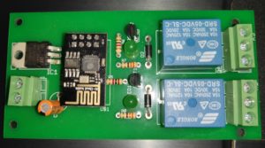
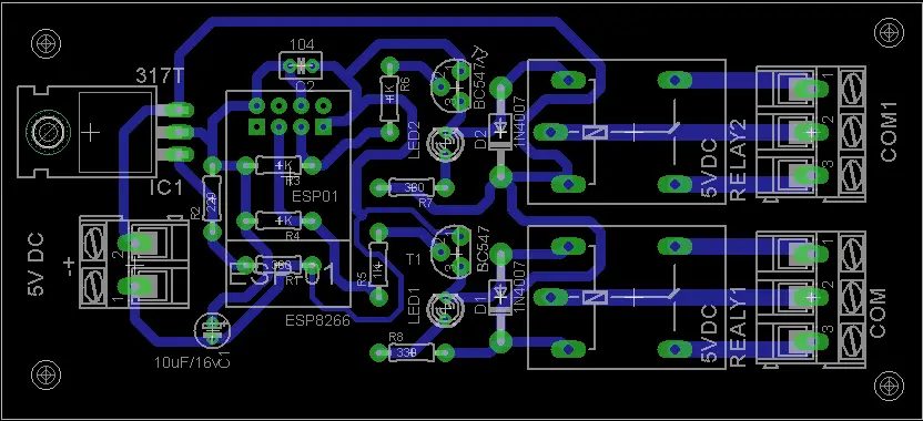
Circuit Diagram
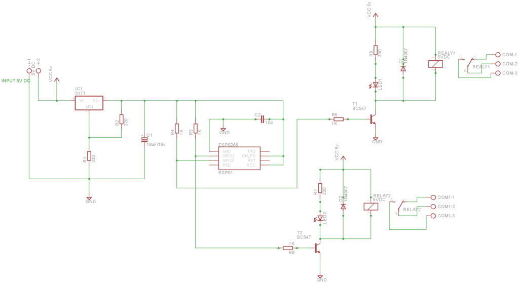
Schematic
PCB View
Interfacing with Blynk App
It is simple to connect the hardware using Blynk app. The Smart Switch using Blynk is a simple project that can be built by any beginner.
Blynk App Configuration
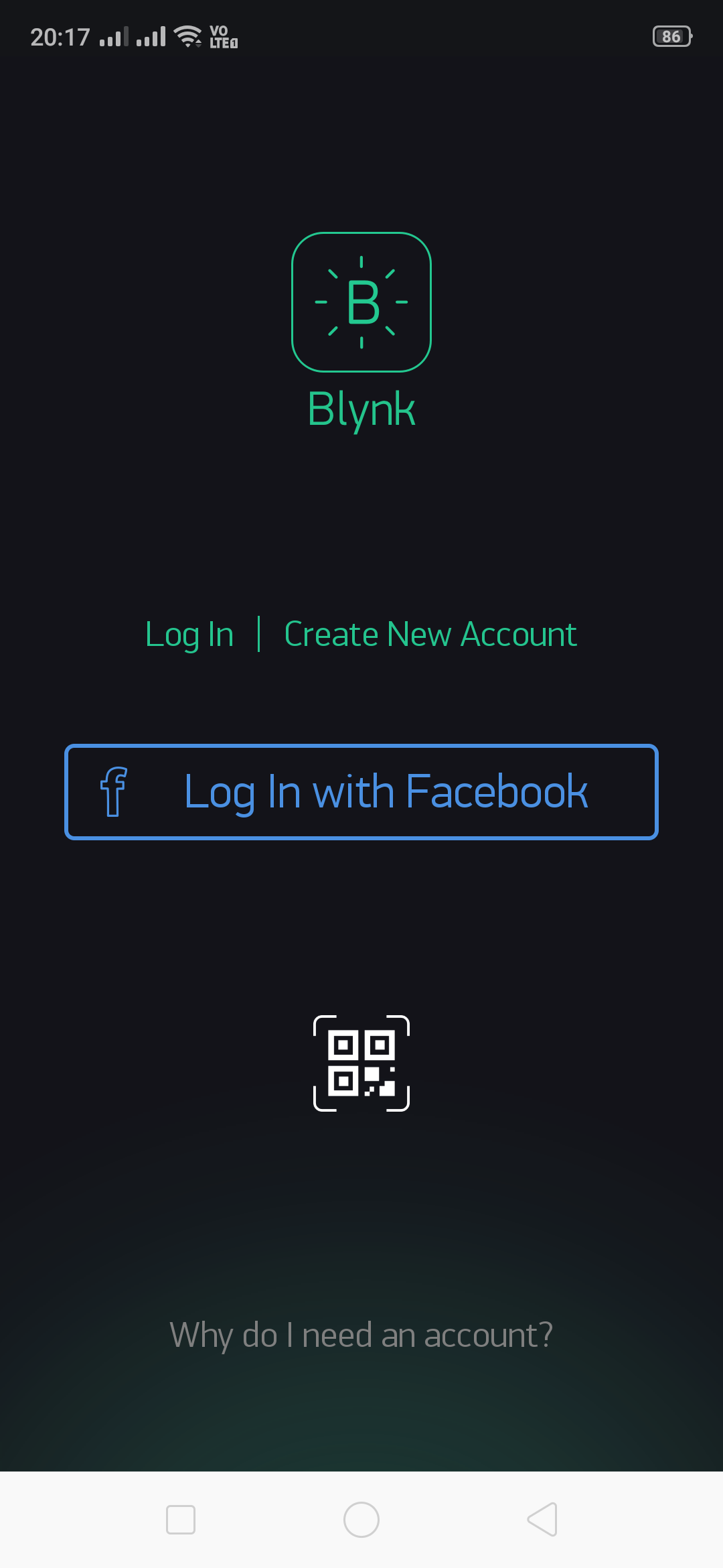
Download the Blynk app and open it. Create an account and login.
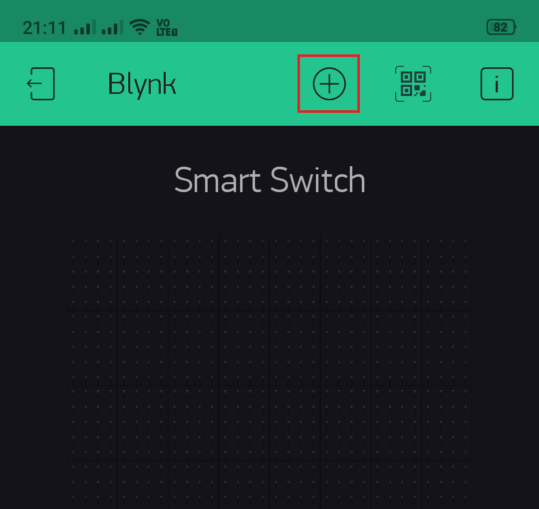
Tap on New Project
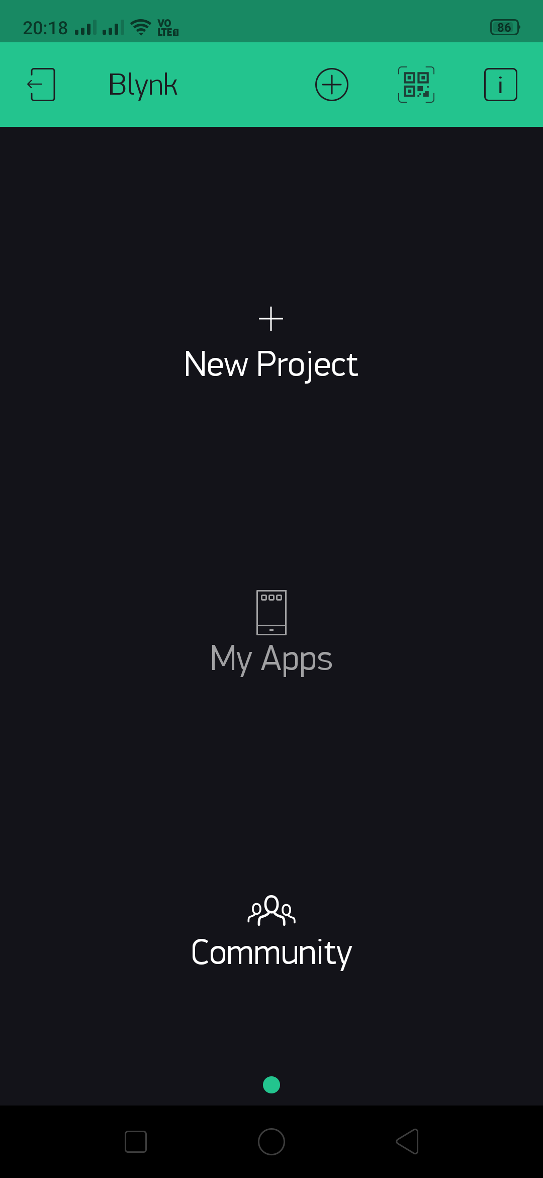
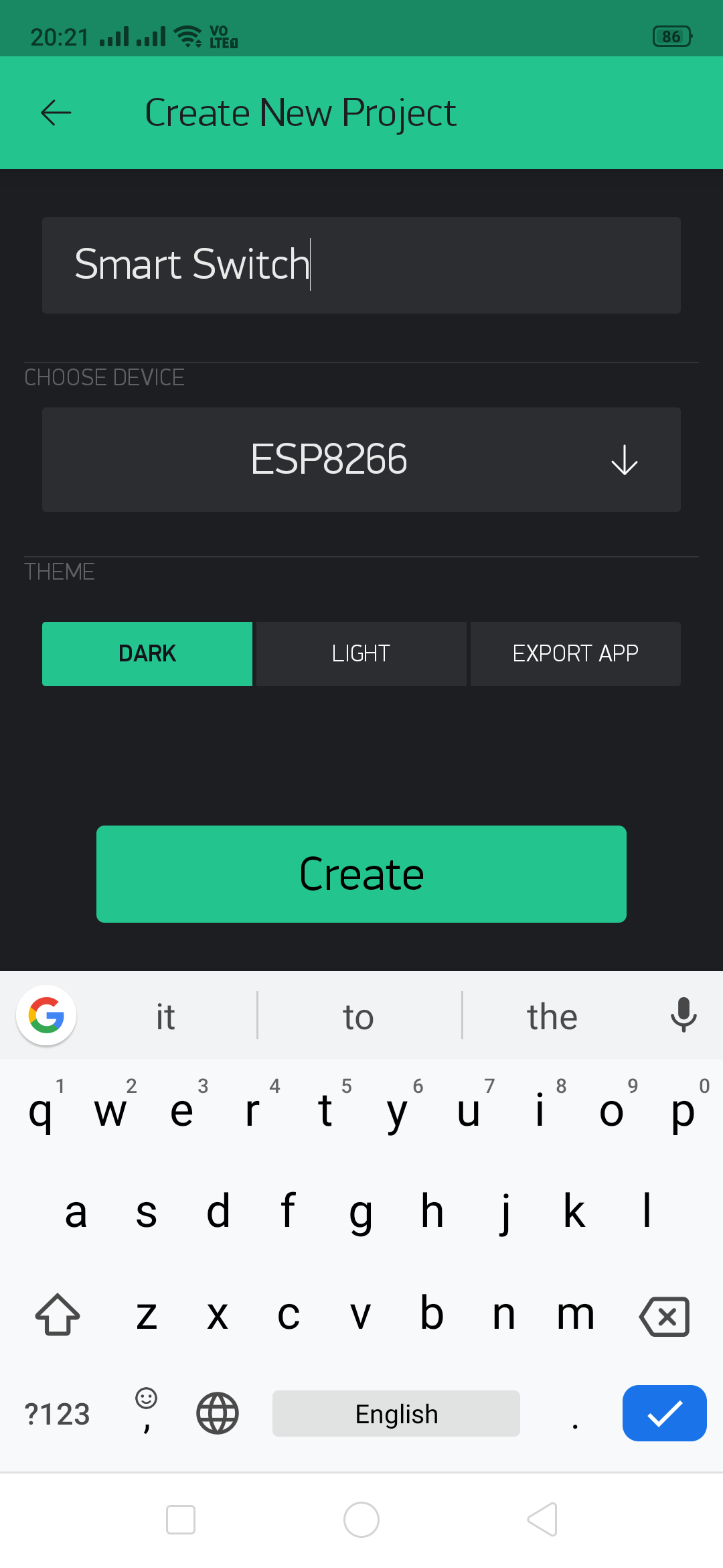
Enter a project name and select a device as ESP8266. We have given Smart Switch. Tap on create.
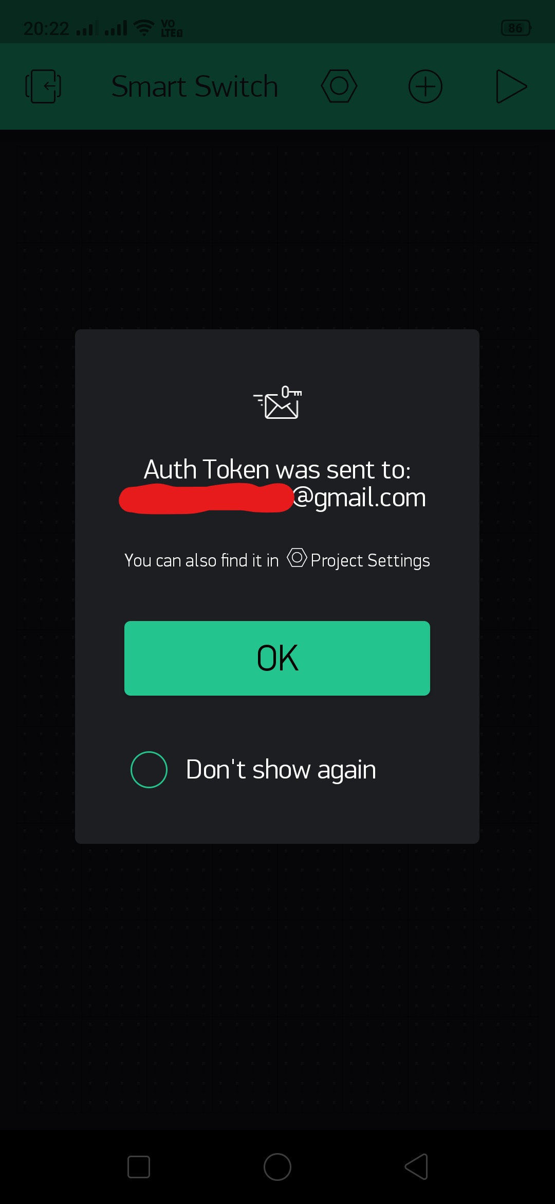
An Auth Token will be sent on your registered email.
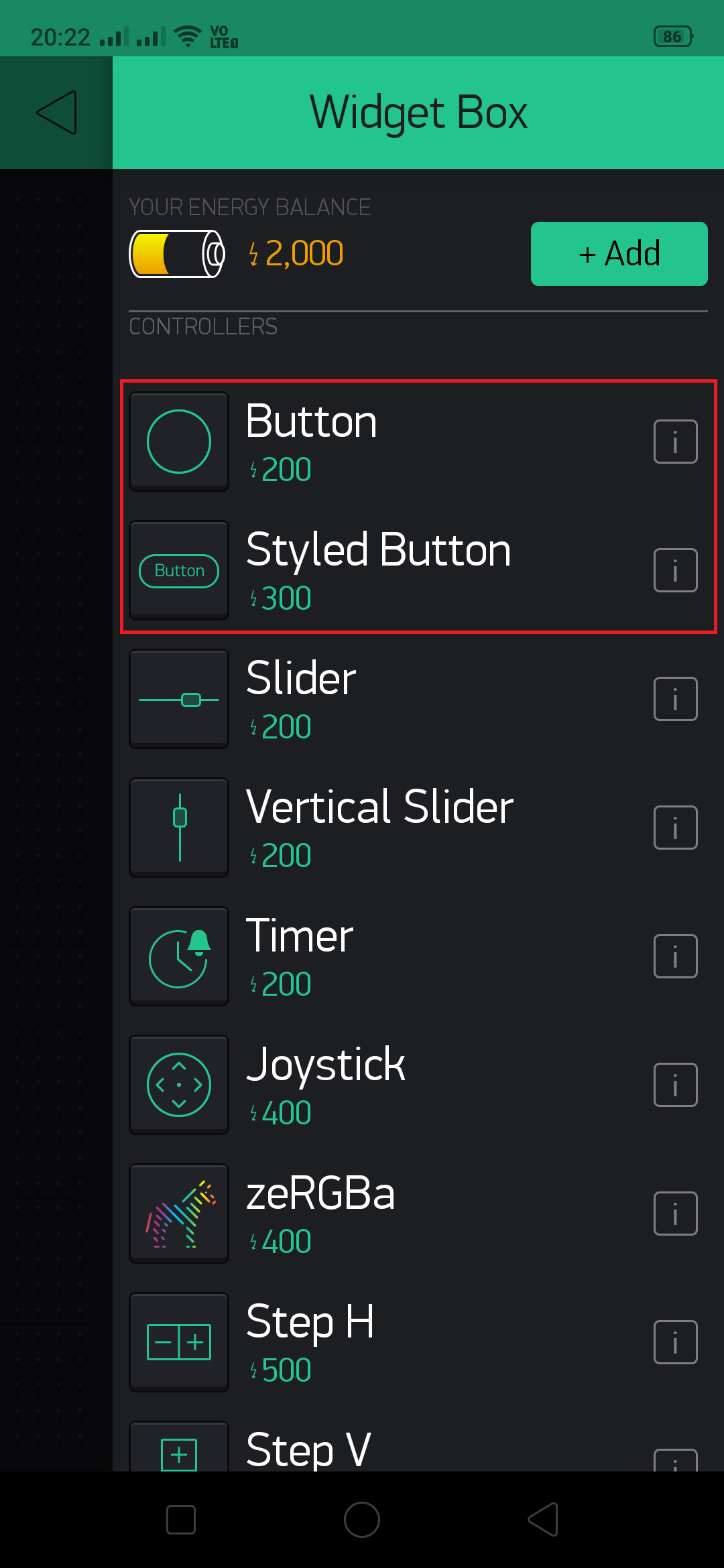
Tap on widget box to add below widgets. For every new user there will be 2000 Energy balance credited, which is enough for this project.
You can select Button or Styled Button
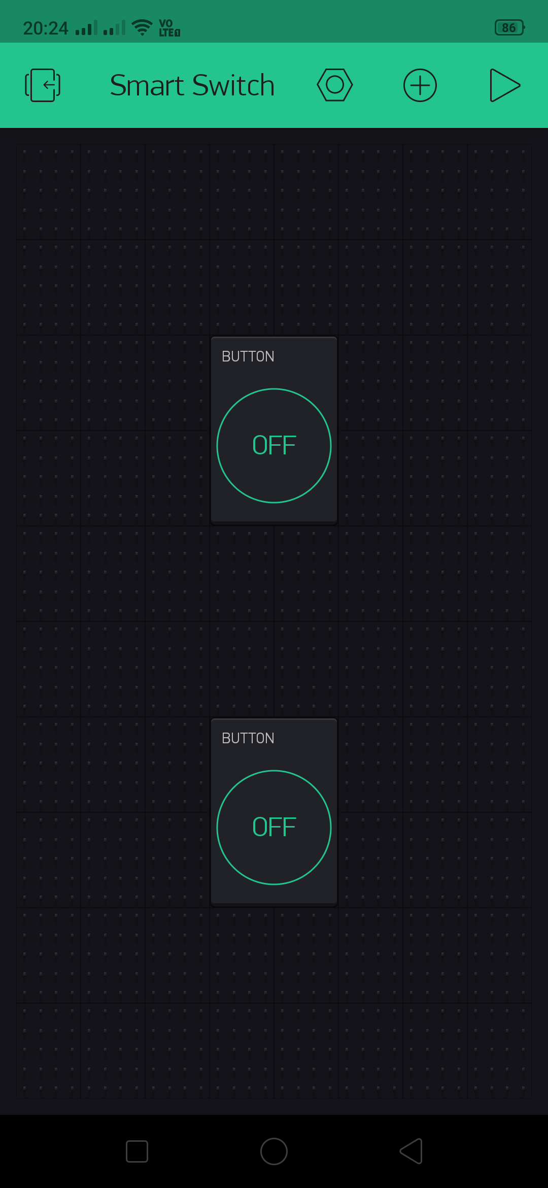
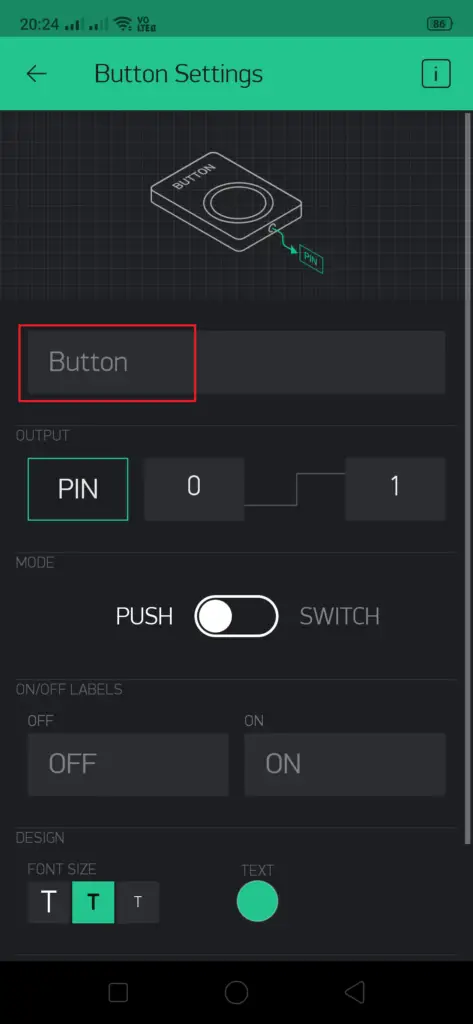
We have selected Button. Tap on the button to configure it.
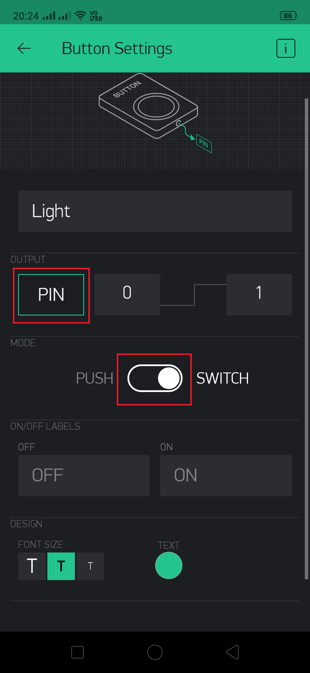
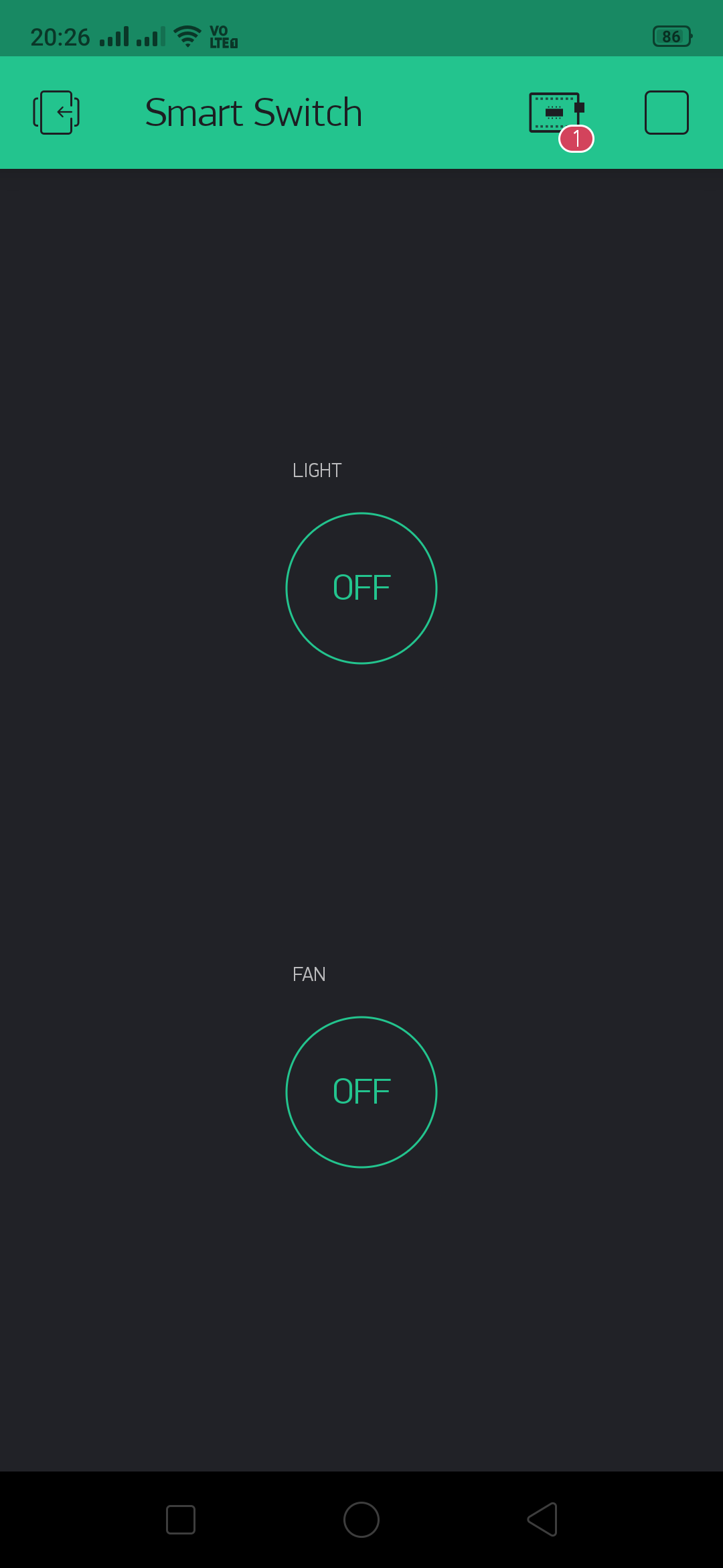
Enter the name of the button. Since we will be using two Buttons, will name it Light and Fan. You can name anything you want. We have given Light.
Change the mode to SWITCH from PUSH. Tap on PIN
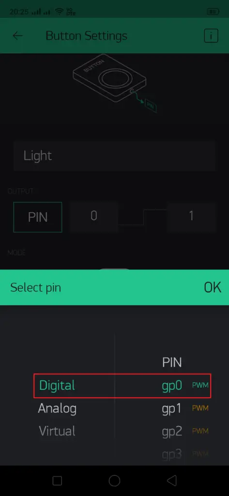
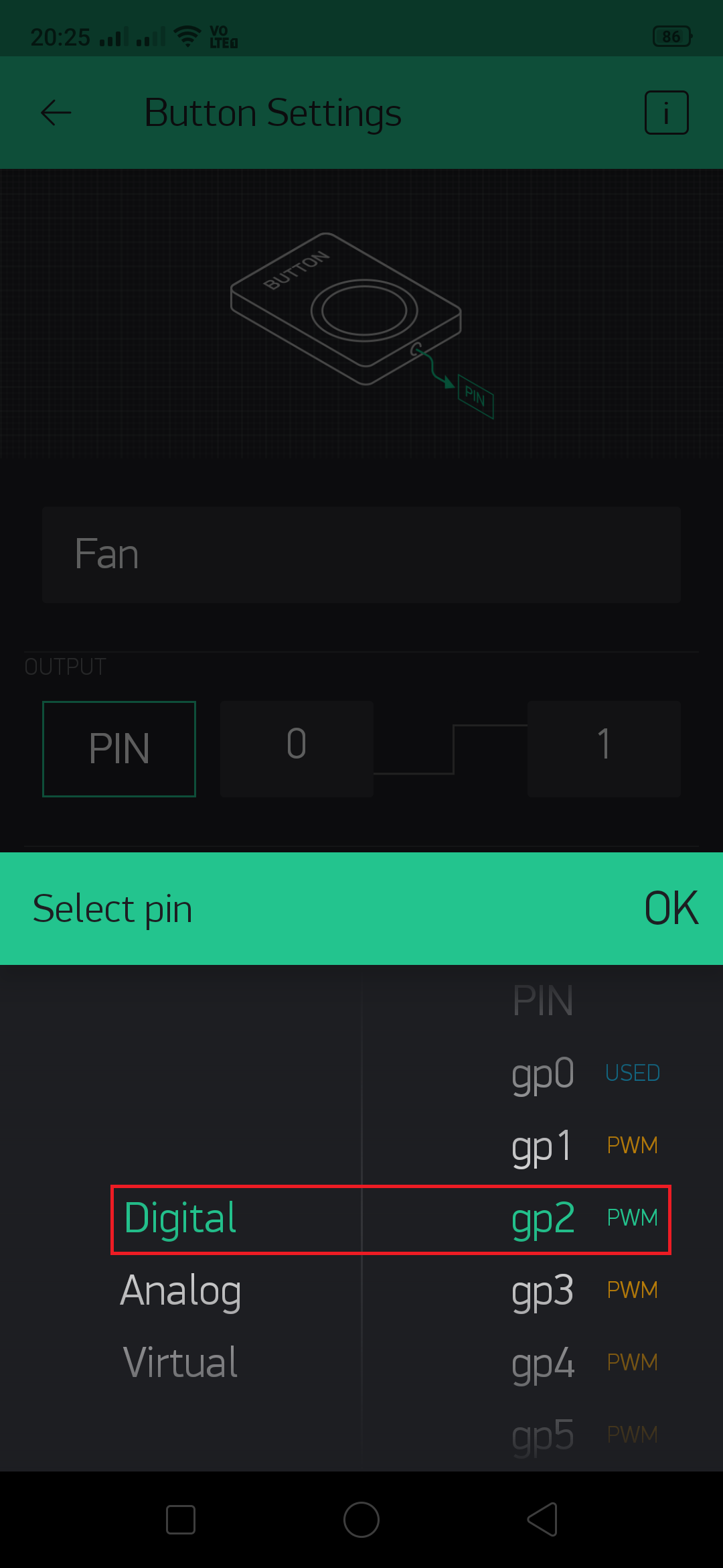
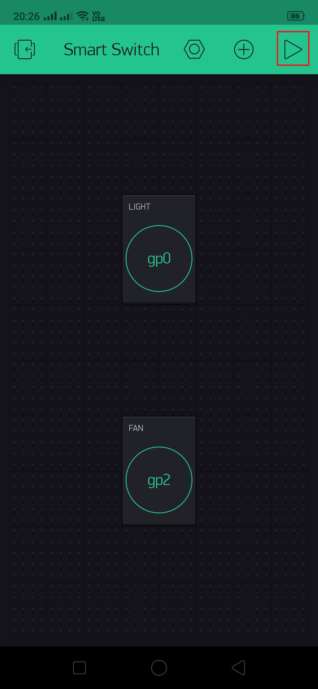
Select the Digital and gp0 for one switch. Repeat the same to configure other switch.
For second switch configure with gp2
Once configuration is done go back. Tap on this Play button highlighted.
The Blynk app configuration is complete now.
Code
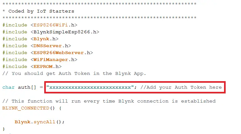
This code is quite simple. We will be using Arduino IDE for uploading the code in ESP8266 module. First copy the Auth Token that you have received while creating this project.
Some more Projects:
- PIR Sensor | How it works?
- PIR based Motion Switch | PIR Sensor Light
- IoT based water level Indicator using ESP8266
- Touch Based Switch board using TTP223
- DHT11 based Temperature Humidity Monitoring IoT Project
- IoT based Door Security Alarm Project with Blynk
- NodeMCU Blynk Feedback Switch with Physical Switch Status
- Telegram NodeMCU based Home Automation
Complete Code
**************************************************************
#Coded by IoT Starters
**************************************************************
#include <ESP8266WiFi.h>
#include <BlynkSimpleEsp8266.h>
#include <Blynk.h>
#include <DNSServer.h>
#include <ESP8266WebServer.h>
#include <WiFiManager.h>
#include <EEPROM.h>
// You should get Auth Token in the Blynk App.

char auth[] = "xxxxxxxxxxxxxxxxxxxxxxxxxx"; //Add your Auth Token here

// This function will run every time Blynk connection is established
BLYNK_CONNECTED()

{
Blynk.syncAll();
}
void setup()
{
//**************************WiFi Manager Code************************
EEPROM.begin(512);
Serial.begin(9600);
WiFiManager wifiManager;
wifiManager.setTimeout(60);
//wifiManager.resetSettings(); //Uncomment this to wipe WiFi settings from EEPROM on boot.Comment out and recompile/upload after 1 boot cycle.

if (!wifiManager.autoConnect("Smart Switch"))
{
delay(3000);
ESP.reset();
delay(5000);
}
Blynk.begin(auth, WiFi.SSID().c_str(), WiFi.psk().c_str());
//*******************************************************************
}

void loop()
{
Blynk.run();
}
Once you edit the code as per Auth Token, then upload it to ESP8266.
Must Read : Simple way to upload code in ESP8266-01
Testing
If you have completed modifying the code with auth token and uploaded the code to ESP8266 module then we will test it now.
Power the circuit and lets connect the module with your wifi connection.
Must Read : How to connect your wifi module using WIFI Manager
Conclusion
With this is project you will be able to learn interfacing ESP8266 with blynk app. This project can be used in real time at home.
