Setting up a LDR sensor with Arduino
Sensors have many applications in everyday life. Light-sensitive sensors or LDRs, perform a specific activity due to changes in light intensity. For example, photocells are used in street light poles. Photocell is a type of light-sensitive variable resistance. With direct and intense radiation of light to the sensor, the resistance between the two bases decreases. With the right coding, you can design a light-sensitive sensor in a professional environment. In this tutorial we will learn Setting up a LDR sensor with Arduino Uno.
Components Required
- Arduino Board [Best Buy]
- LED Any Color
- Resistor 4.7KΩ
- Resistor 330Ω (Optional)
- Jumper Cables [Best Buy]
- Breadboard [Best Buy]
Photocell
Photocell or LDR, when placed in a completely dark environment, its resistance reaches up to 1 MΩ. With light in front of the sensor, its resistance decreases to nearly zero. Under normal conditions of light the resistance reaches 8 to 20 kΩ at its lowest.
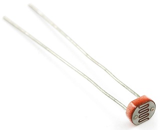
By combining a photocell with a static resistor, a voltage divider is created and finally a variable voltage is created. The numerical value of the sensor can be read by the analog to digital microcontroller converter. The photocell is also known as LDR and has two asset terminals that increase and decrease with the intensity of light, the resistance of both ends of the terminal.
Connecting Photocell with Arduino
Due to the nature of the photocell sensor, ADC microcontroller pins are used to receive data and read values. By ADC we can generate variable voltage and then in the range of 0 to 5 volts DC we get the numerical value of the sensor in each voltage range. This voltage will depend on the resistance of the sensor. A static resistance between 1 and 10 kΩ is suitable, which is the recommended resistance of 4.7 kΩ and 10 kΩ. Pullup one end of the resistor to one of the sensor terminals and the other end of the sensor to the 5V pin in Arduino. In this tutorial, a resistance of 4.7 kΩ has been used.
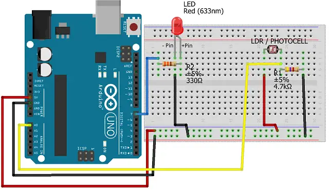
To observe the resistance changes of the photocell sensor in the output, we use an LED.
- Connect the +ve LED pin to pin 7 of the Arduino.
- Attach a pin of the photocell sensor (LDR) to a 4.7 kΩ resistor and then to pin A0 in Arduino.
- Connect the other pin of the photocell sensor directly to the 5V Pullup.
- Connect the remaining resistor pin to the GND with a cable.
Arduino code analysis
This code displays two separate variables. Due to the fact that this sensor can generate variable voltage using ADC, voltage values from 0 to 5 volts can be seen at any time. As the sensor darkens, the base voltage reaches its maximum and it is close to 0 at the lowest.
const int Photocell = A0;

const int LED = 7;

const float VCC = 4.98;

const float R_DIV = 4660.0;

const float DARK_THRESHOLD = 20000.0;
Define input and output
void setup()

{

Serial.begin(9600);

pinMode(Photocell, INPUT);

pinMode(LED, OUTPUT);

}
Variable definition for sensor, variable voltage and resistance
int lightADC = analogRead(Photocell);
float lightV = lightADC * VCC / 1023.0;
float lightR = R_DIV * (VCC / lightV - 1.0);
Condition to activate the LED
if (lightR >= DARK_THRESHOLD)
{
digitalWrite(LED, HIGH);
Serial.println();
delay(1000);
}
else
{
digitalWrite(LED, LOW);
Serial.println();
delay(1000);
}
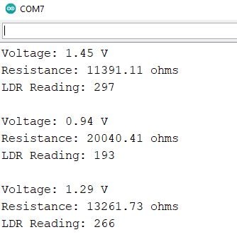
The data received from the sensor in the case of maximum light radiation to the sensor, in this case the base voltage has reached its highest level of 5 volts and the resistance value is 870 ohms, which is greatly reduced. Data received from the sensor in the case of the least amount of light to the sensor. In this case the base voltage has reached its lowest level of 0 volts and the value of the resistance is 8086 ohms, which has increased greatly. Here the voltage in 1.45V where the resistance is at 11391Ω.
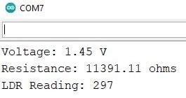
In the same way, by adjusting the light intensity, you can get the appropriate number in your desired environment and define it in constant program values.
Other Interesting Projects:
- Wemos D1 Mini Web Server based Servo Motor Control
- ESP8266 Web Server for Controlling Electrical Devices
- Controlling ESP32 via Bluetooth using Blynk
- Smart Switch using Blynk | IoT Based WiFi Switch
- PIR based Motion Switch | PIR Sensor Light
- IoT based water level Indicator using ESP8266
- Touch Based Switch board using TTP223
- DHT11 based Temperature Humidity Monitoring IoT Project
Arduino Code
Install Arduino software and then create a new tab. Copy the code and transfer it to the Arduino IDE. Depending on the type of board used in the Tools / Board menu, select the type of Arduino used and the port.
const int Photocell = A0;
const int LED = 7;
const float VCC = 4.98;
const float R_DIV = 4660.0;

const float DARK_THRESHOLD = 20000.0;

void setup()
{
Serial.begin(9600);
pinMode(Photocell, INPUT);
pinMode(LED, OUTPUT);
}

void loop()
{

int lightADC = analogRead(Photocell);
if (lightADC > 0)
{

float lightV = lightADC * VCC / 1023.0;
float lightR = R_DIV * (VCC / lightV - 1.0);

Serial.println("Voltage: " + String(lightV) + " V");
Serial.println("Resistance: " + String(lightR) + " ohms");

if (lightR >= DARK_THRESHOLD)
{
digitalWrite(LED, HIGH);
Serial.println();
delay(1000);
}
else
{
digitalWrite(LED, LOW);
Serial.println();
delay(1000);
}
}
}
Construction & Testing
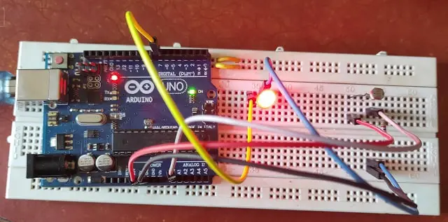
As the sensor darkens, its internal resistance decreases and the output reaches its maximum. In this tutorial, by darkening the sensor, the intensity of the LED light is turned on and when the LDR sensor is exposed to light, the LED turns off.
Conclusion
This is a simple project to understand the concept of connecting a LDR with Arduino. You can also build LDR based light controller projects. The tutorial is for beginners and built with low cost components. These are easily available in the market. Do try this tutorial and comment below.
