Introduction
New developments board are introduced every year. Getting proper IDE or software for uploading code in these new development boards are challenging. Arduino has been a great platform to integrate these kind of development boards and upload codes.
In this article we will see ESP32 programming using Arduino IDE. We all are in world of smartphones and smart devices. As per recent study the number of electronic devices connected to internet is twice the number of people using internet. The connectivity if devices with internet is make it smarter. Almost 20 billion devices will be connected to internet by the end of this year. For electronic enthusiast the open source platforms like Arduino and Espressif Systems has made things too easy for developing new IoT projects.
ESP8266-01 was launched couple of years back by Espressif Systems. This chip and wifi module provided a great support to many hobbyists to connect their devices to internet. Since then this community has been developing rapidly. Using ESP32, many other devices and development boards have been introduced in the market. After launching of ESP32 chip and development boards by Espressif, the level of IoT have moved to a new level.
Now lets get started with ESP32 programming using Arduino IDE.
Hardware Details of ESP32
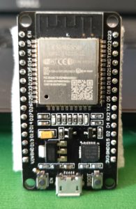
ESP32 is one of the most powerful chip developed. It is bigger than ESP8266-01. Pins are completely breadboard friendly. It has good number of Input/output pins. Lets take a look at the board more closely. This development board has couple of buttons and led’s as well. The function of these are explained below.
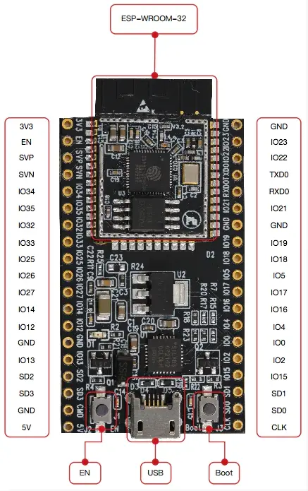
ESP-WROOM-32:
This is the brain of this module. This is a Tensilica Xtensa 32-bit LX6 microprocessor which is developed by Espressif systems. If you want to know in depth about ESP32 chip then please refer ESP-WROOM-32 Datasheet. This has a clock frequency of up to 240 MHz.
EN Button:
This button is also known as reset. It will rest the code running in ESP32 module.
Boot Button:
This is used to upload programs to this module. When Arduino will start uploading the sketch, you have to keep it pressed until it stats loading in Arduino IDE.
if you press both the buttons together i.e. Boot and EN, the modules enters to firmware uploading mode.
Red LED:
Red LED will glow once the module is powered ON. This is a power indicator.
Blue LED:
Blue LED is connected to GPIO pin and it can be turned on/off using programs.
Peripherals and I/O:
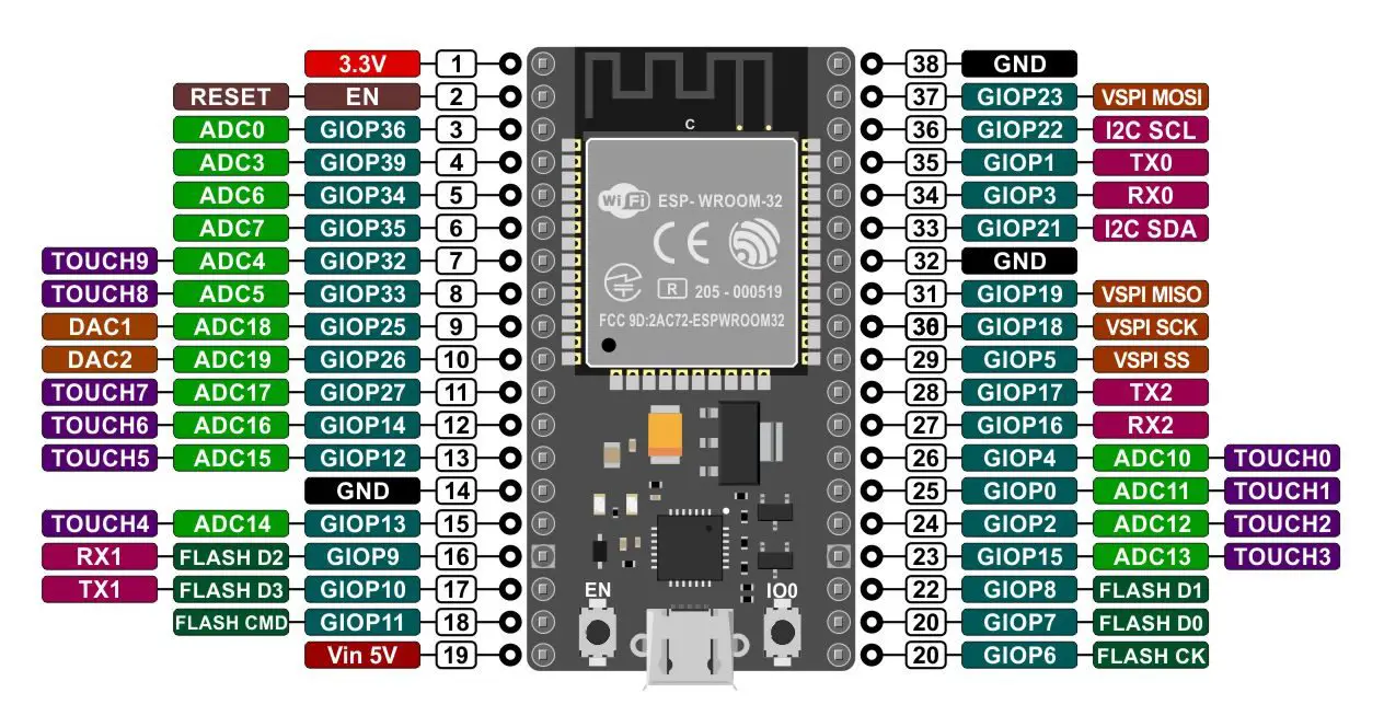
ESP32 has total 48 GPIO pins, out of which 25 of them are present as pin headers on both sides of the module. These pins are capable of below uses
- 15 channels of 12-bit SAR ADC’s
- 2 UART interfaces
- 25 channels of PWM pins
- 2 8-bit DACs to produce true analog voltages.
- 3 SPI and 1 I2C interfaces to connect sensors and peripherals
- 9 GPIOs for capacitive touch sensing.
If you are a deep learner then you can follow ESP32 Datasheet.
Micro USB:
This module is equipped with a micro usb jack. This jack heps in connecting this module with computer for uploading codes easily. All you need is a micro usb cable. This jack can also used for serial communication. It has a CP2102 USB-to-UART converter which supports 5 Mbps communication speed.
Below are the technical details of ESP32
ESP32 |
|
| Specification | Value |
| Number of cores | 2 |
| Architecture | 32 bit |
| RAM | 512 KB |
| FLASH | 16 MB |
| GPIO Pins | 36 |
| Wi-Fi | 802.11 b/g/n/e/i (802.11n @ 2.4 GHz up to 150 Mbit/s) |
| Bluetooth | v4.2 BR/EDR and Bluetooth Low Energy (BLE) |
| ADC channels | 18 channels |
| ADC Resolution | 12-bit |
| DAC channels | 2 |
| DAC Resolution | 8-bit |
| Communication Protocols | SPI, IIC, I2S, UART, CAN |
Parts Required
- ESP32 Module
- Arduino IDE
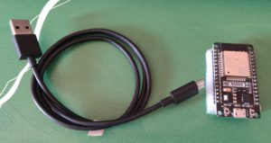
- Micro USB cable
Arduino Setup
First we need to setup Arduino IDE for uploading code in ESP32
Go to File -> Preference
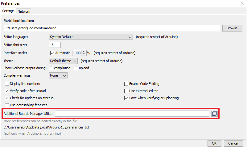
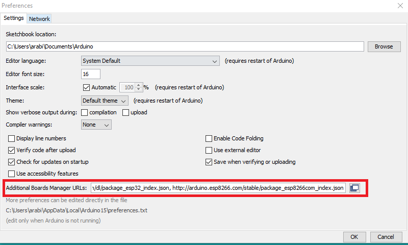
Copy below URL’s and paste it in Additional Boards Manager URL’s
https://dl.espressif.com/dl/package_esp32_index.json,
http://arduino.esp8266.com/stable/package_esp8266com_index.json
Once you paste it, Click on OK
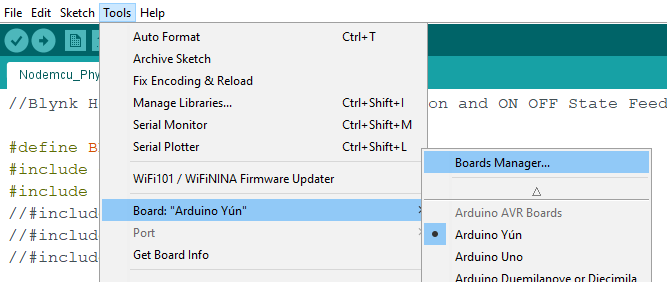
Now we need to add ESP32 board from Boards Manager
Tools -> Board -> Boards Manager
After opening Boards Manager type ESP32 in search box
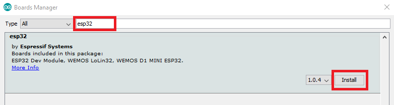
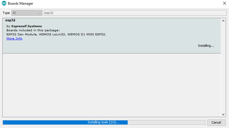
You will find ESP32 By Espressif Systems click on Install. It will start installing
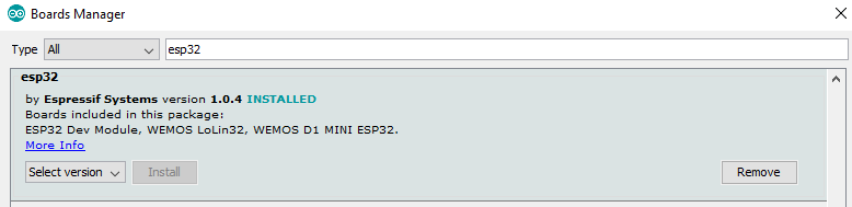
Soon it will be marked as INSTALLED
Now lets search for ESP32 boards.
Go to Tools -> Board
Scroll down and search for ESP32 Dev Module. Select it
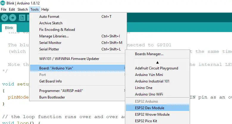
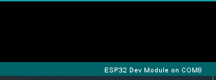
After selection you will see the same in right hand bottom corner
Connect you ESP32 Module with computer using USB cable

Connection
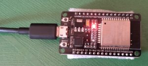
Connect one end of the cable with micro USB and other end with your laptop or computer.
Code
If you have connected you ESP32 module with your computer and configured Arduino IDE with above configurations, then you are almost ready to upload your first code. Below code will blink the blue led.
int LED_BUILTIN = 2;
void setup()
{
pinMode(LED_BUILTIN, OUTPUT); // Initialize the LED_BUILTIN pin as an output
}
void loop() // the loop function runs over and over again forever
{
digitalWrite(LED_BUILTIN, LOW); // Turn the LED on
delay(1000); // Wait for a second
digitalWrite(LED_BUILTIN, HIGH); // Turn the LED off
delay(1000); // Wait for a seconds
}
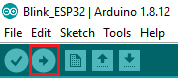
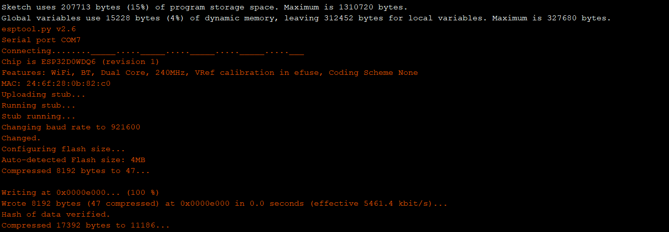
Uploading Code
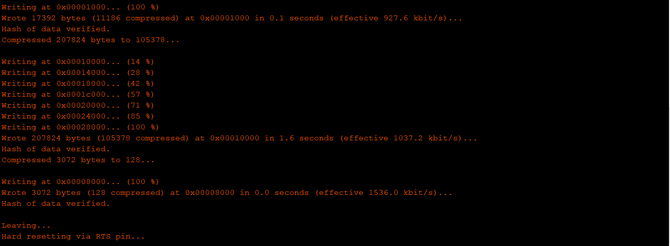
Testing
Once code is uploaded successfully, we will see the blue light starts blinking. This indicate the code is uploaded correctly and working fine. ESP32 programming using Arduino IDE is completed.


Hi, There is an error while uploading the code can you help me out
esptool.py v3.0-dev
Serial port COM7
Connecting…….._____….._____….._____….._____….._____….._____….._____
A fatal error occurred: Failed to connect to ESP32: Timed out waiting for packet header
A fatal error occurred: Failed to connect to ESP32: Timed out waiting for packet header
Press the EN button till you see the start of code upload